STM8S: Porovnání verzí
Skočit na navigaci
Skočit na vyhledávání
Bez shrnutí editace |
Bez shrnutí editace |
||
| Řádek 8: | Řádek 8: | ||
<source lang="C"> | <source lang="C"> | ||
void setup() { | void setup() { | ||
// initialize digital pin LED_BUILTIN as an output. | pinMode(3, OUTPUT); // initialize digital pin LED_BUILTIN as an output. | ||
} | } | ||
void loop() { | void loop() { | ||
digitalWrite(3, LOW); // turn the LED on | digitalWrite(3, LOW); // turn the LED on | ||
delay(1000); | delay(1000); // wait for a second | ||
digitalWrite(3, HIGH); | digitalWrite(3, HIGH); // turn the LED off | ||
delay(1000); | delay(1000); // wait for a second | ||
} | } | ||
</source> | |||
example: | more example: [https://tenbaht.github.io/sduino/ sduino] ([https://tenbaht.github.io/sduino/api/LiquidCrystal/ LCD], [https://tenbaht.github.io/sduino/api/Stepper/ Stepper], [https://tenbaht.github.io/sduino/api/Servo/ Servo]) | ||
Verze z 25. 11. 2020, 18:12
Arduino Pin Mapping for STM8S103F3
Programming STM8S Microcontrollers using Arduino IDE
void setup() {
  pinMode(3, OUTPUT);     // initialize digital pin LED_BUILTIN as an output.
}

void loop() {
  digitalWrite(3, LOW);   // turn the LED on
  delay(1000);            // wait for a second
  digitalWrite(3, HIGH);  // turn the LED off
  delay(1000);            // wait for a second
}
more example: sduino (LCD, Stepper, Servo)


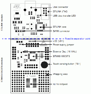
STM8S-Discovery - vývojový kit STM
MCU: 8 bit mikrokontrolér typu STM8S105
Kit obsahuje:
- USB interface / programátor
- dotykový senzor
- uživatelská LED
- vývojová plocha
- další prvky
Základní vlastnosti STMicroelectronics STM8S-Discovery Kit:
- Mikrokontrolér STM8S105C6T6 s 32 KB Flash, 2 KB RAM a 1 KB EEPROM
- Jednoduché napájecí z USB portu
- Volitelné napětí 5 V nebo 3,3 V pro vaši aplikaci
- Rozšířený STLink pro STM8S
- USB rozhraní pro programování a ladění
- Podpora ladění SWIM
- Kapacitní dotykový senzor
- Uživatelská LED
- Rozšiřující headery pro všechny I/O piny
- Vývojová plocha pro vytvoření jednoduché uživatelské aplikace
- Velmi nízká cena nepřekračuje 5 EUR
STM8 Family Features include:
- 24MHz Harvard architecture CPU
- Wide operating voltage range from 1.65V to 5V ¹
- 5V: Run current 1mA + (0.6mA x MHz) (typical) ¹
- 3V: Run current 1mA + (0.4mA x MHz) (typical) ¹
- Wait Current 1.6mA - CPU not clocked, all peripherals running ¹
- Halt Mode current 10µA typical, 25µA max ¹
- Average 1.8 cycles/instruction
- 8-bit ALU
- 3-stage CPU pipeline
- Single cycle fetch for most instructions
- Flash Memory with write protect
- Read Out Protection - blocks reading out memory contents, erases Flash and RAM if override is attempted
- True Data EEPROM
- 32-bit Program Memory Bus
- 24-bit Program Counter
- Up to 256KBytes of on-chip Flash Program Memory
- 16-bit stack pointer with relative addressing
- 16-bit X and Y index registers for indirect addressing
- 20 addressing modes
- 32 Interrupt Vectors, 3 priority levels.
- Internal 16MHz RC oscillator
- Internal 128KHz oscillator
- Low Power modes
- 8x8 multiplication
- 16/8 and 16/16 divide
- Single Wire debug
The STM8 uses many of the same modular peripherals as ST's 32-bit product line. STM8 available peripherals include:
- Clock Security System (CSS) protects against clock failure
- Dual Watchdog timers each with independent clock sources
- 16-bit CAPCOM timers with up to 4 CAPCOM channels per timer
- a CAPCOM channel can be IC, OC, or PWM
- 16-bit PWM timers with 3 complimentary outputs and adjustable dead time for inverter control and BLDC
- 10-bit (±3-bits) SAR A/C with 7µsec conversion time
- 8-bit System Timer
- Single or continuous conversion
- Analog watchdog function
- Scan mode
- USART supports SPI, LIN (master)
- LIN-UART (LIN master/slave) with automatic synchronization
- SPI @ up to 10 Mbits/sec
- I2C @ 400Kbits/sec
- IrDA
- SMBUS
- PMBUS
- Bootloader for in-circuit Flash programming through UART, LIN, and CAN
- CAN (2.0A.B) @ 1 Mbits/sec
www:
- Začínáme s STM8S 1 - seriál na MCU.cz atd....vše na mcu.cz
