BOB-Corridor Sensing
original: http://forums.parallax.com/showthread.php?128172-Boe-Bot-Robot-Corridor-Navigation
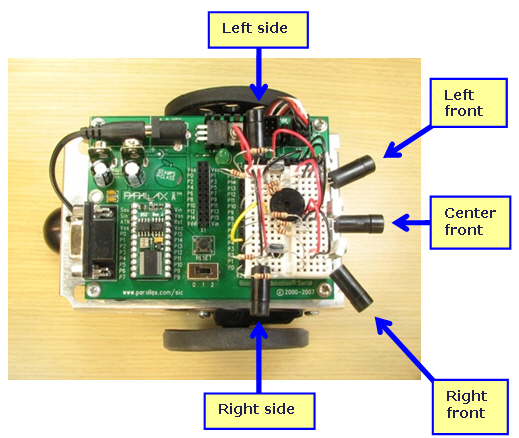
The left front and right front sensors on the Boe-Bot are probably familiar from Robotics with the Boe-Bot chapters 7 and 8. Activities in those chapters used them for object avoidance, drop-off avoidance, and object following. For corridor navigation, we’ll use them to decide when to veer away from the corridor’s walls. Then, the left side, center front, and right side detectors can be used for detecting the difference between a wall and a corridor opening.
Obsah |
Circuit
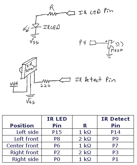
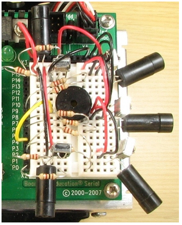
The corridor sensing circuit requires the two IR object detection sensors in the Robotics with the Boe-Bot kit along with three extra ones. If you need to buy three additional IR object detectors, the IR Receiver and IR Transmitter Assembly in the Parts List are linked to their product pages. The schematic shows one copy of the IR circuit and the table below it lists the I/O pin connections and IR LED series resistor values for each detector. Below that, there’s a placement and wiring close-up picture that will help with building the circuit.
Parts List
- (5) Resistors – 220 Ω (red-red-brown)
- (3) Resistors – 1 kΩ (brown-black-red)
- (2) Resistors – 2 kΩ (red-black-red)
- (5) IR Receiver
- (5) IR Transmitter Assembly Kits
- (IR LEDs, standoffs and shields)
- (misc) Jumper wires
Schematic
There are five copies of the IR LED and IR Detect circuits on the breadboard. Use the table below for I/O pin connections and series resistance values in the IR LED circuits.
Placement and Wiring
Testing the Corridor Sensing Circuit
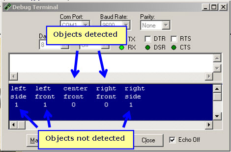
Before navigating any corridors, make sure to test your circuit with the Display program below. Each sensor location should display a 1 when there’s no object within a few inches of it, and 0 when there is an object.
√ Run Test IR Detection.bs2.
√ Verify that each detector displays 1 when no object is in front of it and 0 when there is an object in front of it.
√ Find an fix any circuit mistakes that might be preventing your IR detection circuits from working before you continue to the next program.
Code:
' File: Test IR Detection.bs2

' {$STAMP BS2}
' {$PBASIC 2.5}

i              VAR     Nib
pinIrLed       VAR     Nib
pinIrDet       VAR     Nib
ir             VAR     Bit
obj            VAR     Bit(5)
x              VAR     Byte

FREQOUT 4, 1000, 3000

DEBUG "left  left   center  right  right", CR,
      "side  front  front   front  side"

DO
  GOSUB Wall_Detect
  GOSUB Wall_Sensor_Display
LOOP

Wall_Detect:
  FOR i = 4 TO 0
    LOOKUP i, [15, 8, 6, 2, 0], pinIrLed
    LOOKUP i, [14, 9, 7, 3, 1], pinIrDet
    FREQOUT pinIrLed, 1, 37500
    ir = IN0(pinIrDet)
    obj(i) = ir
  NEXT
  RETURN

Wall_Sensor_Display:
  FOR i = 4 TO 0
    LOOKUP i, [1, 8, 15, 23, 29], x
    DEBUG CRSRXY, x, 2, BIN1 obj(i)
  NEXT
  PAUSE 20
  RETURN
Calibrate Corridor Sensing
Now that the sensors work, they still need to be adjusted to sense a corridor. A good corridor for this circuit is two walls 12 inches apart. The Test Basic Corridor.bs2. program just monitors the right front and left front IR detectors, and makes the Boe-Bot turn slightly to correct its direction if it’s going toward one of the walls or getting too close.
The most important part of this calibration is pointing your left front and right front IR LEDs and detectors in the right direction. If they are pointing too far right/left, they might see the walls all the time and the Boe-Bot will seem confused and move forward very slowly, if at all. If they are pointing too far forward, they won’t detect a wall until it’s too late and the Boe-Bot is already sliding along the wall.
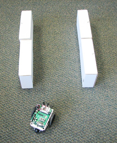
Your adjustments will be correct if you can send your Boe-Bot into a corridor like this at the angle shown (ether from the left or right), and it straightens itself out and makes it through the 12 inch wide corridor.
√ Run Test Corridor Wall Avoidance.bs2. √ Start running your Boe-Bot through the corridor. If it seems to stall, it’s probably seeing too much wall, and the left front and right front IR detectors need to be turned more in the straight ahead direction. √ If it gets so close to the wall that you say “uh-oh”, or if it runs into the wall, the left front and right front sensors need to be turned slightly outward. √ Keep adjusting until you can send it in at the angle shown in the picture above. It should be able to straighten itself out and go all the way through the corridor, regardless of whether it’s coming info the corridor from the left or the right.
Code:
' File: Test Corridor Wall Avoidance.bs2
' {$STAMP BS2}
' {$PBASIC 2.5}

' Constants

L_S CON 0 : L_F CON  1 : C_F CON 2 : R_F CON 3 : R_S CON 4
Fwd CON 0 : Veer_R CON 1 : Veer_L CON 2: Turn_L CON 3 : Turn_R CON 4
U_Turn CON 5 : FreqFar CON 37500 : FreqNear CON 40500

' Variables

pulseLeft      VAR     Word
pulseRight     VAR     Word
freq           VAR     Word
go             VAR     Byte
reps           VAR     Byte
i              VAR     Byte
pinIrLed       VAR     Nib
pinIrDet       VAR     Nib
wall           VAR     Bit(5)
ir             VAR     Bit

' Initialization

FREQOUT 4, 1000, 3000
DEBUG "Program running!"
freq = FreqFar

' Main Routine

DO
  GOSUB Wall_Detect
  IF (wall(L_F)=1 AND wall(R_F)=1) OR (wall(L_F)=0 AND wall(R_F)=0) THEN
    go = fwd
  ELSEIF wall(L_F) = 0 THEN
    go = Veer_R
  ELSEIF wall(R_F) = 0 THEN
    go = Veer_L
  ENDIF
LOOP

' Subroutine: Wall_Detect

Wall_Detect:
  FOR i = L_S TO R_S
    LOOKUP i, [15, 8, 6, 2, 0], pinIrLed
    LOOKUP i, [14, 9, 7, 3, 1], pinIrDet
    LOOKUP i, [FreqFar, FreqNear, FreqNear, FreqNear, FreqFar], freq
    FREQOUT pinIrLed, 1, freq
    ir = IN0(pinIrDet)
    wall(i) = ir
  NEXT
  RETURN

' Subroutine: Maneuver

Maneuver:    'Fwd,  Veer_R, Veer_L, Turn_L, Turn_R, U_Turn
  LOOKUP go, [1,    1,      1,      65,     65,     40 ], reps
  LOOKUP go, [850,  850,    750,    765,    850,    850], pulseLeft
  LOOKUP go, [650,  750,    650,    650,    735,    850], pulseRight
  FOR i = 1 TO reps
    PULSOUT 13, pulseLeft
    PULSOUT 12, pulseRight
    PAUSE 20
  NEXT
  RETURN