STM8S
Z MediaWiki SPŠ a VOŠ Písek
(Rozdíly mezi verzemi)
| (Není zobrazeno 19 mezilehlých verzí od 1 uživatele.) | |||
| Řádka 1: | Řádka 1: | ||
| + | |||
| + | |||
| + | {| class="toccolours" cellpadding="5" style="float: right; clear: right; margin: 0 0 1em 1em; font-size: 85%; width: 25em" | ||
| + | | colspan="2" style="text-align: center; font-size: larger; background-color: lightgreen;" | '''''STM8S103F3''''' | ||
| + | |- | ||
| + | |||
| + | | colspan="2" style="text-align: center;" | | ||
| + | |- style="vertical-align: top;" | ||
| + | | | ||
| + | [[Soubor:STM8S103F3_002.jpg|300px]] | ||
| + | |||
| + | [[Soubor:STM8S103F3_003.jpg|300px]] | ||
| + | |||
| + | |||
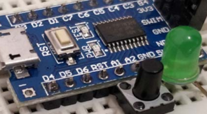
| + | * Boardname stm8blue | ||
| + | * CPU STM8S103F3P6 | ||
| + | * Clock 16MHz, internal oscillator | ||
| + | * Flash 8kB | ||
| + | * RAM 1kB | ||
| + | * EEPROM 640 byte | ||
| + | * I/O voltage 3.3V | ||
| + | * GPIO 14 | ||
| + | * serial connections UART, SPI, I2C | ||
| + | * PWM 4 (up to 7 via alternate mapping) | ||
| + | * ADC 5 channel, 10 bit | ||
| + | * LED PB5 (Arduino D3), active low, shared with I2C, red | ||
| + | |||
| + | |} | ||
| + | |||
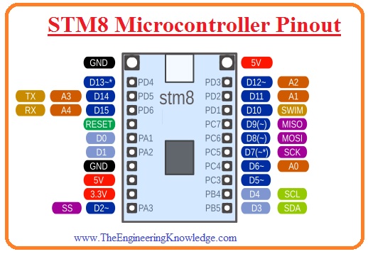
Arduino Pin Mapping for STM8S103F3 | Arduino Pin Mapping for STM8S103F3 | ||
| − | [[Soubor:STM8S103F3_001.jpg | + | [[Soubor:STM8S103F3_001.jpg|Arduino Pin Mapping for STM8S103F3|link=https://www.theengineeringknowledge.com/introduction-to-stm8-microcontroller/]] |
[https://circuitdigest.com/microcontroller-projects/programming-stm8s-microcontrollers-using-arduino-ide Programming STM8S Microcontrollers using Arduino IDE] | [https://circuitdigest.com/microcontroller-projects/programming-stm8s-microcontrollers-using-arduino-ide Programming STM8S Microcontrollers using Arduino IDE] | ||
| − | <source lang=" | + | set: https://github.com/tenbaht/sduino/raw/master/package_sduino_stm8_index.json |
| + | |||
| + | [https://navody.arduino-shop.cz/navody-k-produktum/vyvojova-deska-stm8s103f3.html Vývojová deska STM8S103F3] | ||
| + | |||
| + | |||
| + | <source lang="C"> | ||
void setup() { | void setup() { | ||
| − | // initialize digital pin LED_BUILTIN as an output. | + | pinMode(3, OUTPUT); // initialize digital pin LED_BUILTIN as an output. |
| − | + | ||
} | } | ||
| − | + | ||
void loop() { | void loop() { | ||
| − | digitalWrite(3, LOW); // turn the LED on | + | digitalWrite(3, LOW); // turn the LED on |
| − | delay(1000); | + | delay(1000); // wait for a second |
| − | digitalWrite(3, HIGH); | + | digitalWrite(3, HIGH); // turn the LED off |
| − | delay(1000); | + | delay(1000); // wait for a second |
} | } | ||
| + | </source> | ||
| − | example: | + | SDUINO example: |
| − | [https://tenbaht.github.io/sduino/ sduino] | + | * [https://tenbaht.github.io/sduino/ sduino] |
| + | * [https://tenbaht.github.io/sduino/api/LiquidCrystal/ LCD] | ||
| + | * [https://tenbaht.github.io/sduino/api/I2C/ I2C] | ||
| + | * [https://tenbaht.github.io/sduino/api/Stepper/ Stepper] | ||
| + | * [https://tenbaht.github.io/sduino/api/Servo/ Servo] | ||
| + | * [https://tenbaht.github.io/sduino/api/LiquidCrystal_I2C/ LiquidCrystal_I2C Library] | ||
| + | <source lang="C"> | ||
| + | //TESTED ttps://tenbaht.github.io/sduino/api/LiquidCrystal_I2C/ | ||
| + | |||
| + | #include <Arduino.h> | ||
| + | #include <LiquidCrystal_I2C.h> | ||
| + | |||
| + | // initialize the library with the I2C bus address | ||
| + | // The instance name "lcd" is *within* the brackets | ||
| + | LiquidCrystal_I2C (lcd,0x27,16,2); | ||
| + | |||
| + | void setup() { | ||
| + | lcd_begin(); | ||
| + | lcd_print_s("hello, world!"); | ||
| + | } | ||
| + | |||
| + | |||
| + | void loop() { | ||
| + | lcd_setCursor(0, 1); | ||
| + | lcd_print_u(millis() / 1000); | ||
| + | } | ||
</source> | </source> | ||
| + | |||
| + | [[Soubor:STM8_Cosmic_01.png|300px|link=https://circuitdigest.com/tags/stm8]] | ||
| + | |||
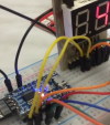
| + | * [https://circuitdigest.com/tags/stm8 STM8S using Cosmic C] | ||
| + | * [https://circuitdigest.com/microcontroller-projects/gpio-functions-on-stm8s-using-cosmic-c-and-spl-blinking-led-with-push-button Blinking and Controlling LED with Push Button] | ||
| + | |||
| + | |||
| Řádka 31: | Řádka 97: | ||
[[Soubor:SMT8S_004.jpg|thumb]] | [[Soubor:SMT8S_004.jpg|thumb]] | ||
[[Soubor:SMT8S_005.jpg|thumb]] | [[Soubor:SMT8S_005.jpg|thumb]] | ||
| + | |||
| + | |||
| + | |||
| + | [[Soubor:SOC_2021_VYS_14.png|100px|Video|link=http://wiki.sps-pi.cz/images/1/15/SOC_2021_VYS_14.mp4]] | ||
| + | |||
| + | [[:Media:SOC_2021_VYS_14.pdf|Sada úloh s STM8S]] | ||
| + | |||
| + | |||
'''STM8S-Discovery - vývojový kit STM''' | '''STM8S-Discovery - vývojový kit STM''' | ||
Aktuální verze z 1. 4. 2021, 13:10
| STM8S103F3 | |
|
| |


Arduino Pin Mapping for STM8S103F3
Programming STM8S Microcontrollers using Arduino IDE
set: https://github.com/tenbaht/sduino/raw/master/package_sduino_stm8_index.json
void setup() {
  pinMode(3, OUTPUT);     // initialize digital pin LED_BUILTIN as an output.
}

void loop() {
  digitalWrite(3, LOW);   // turn the LED on
  delay(1000);            // wait for a second
  digitalWrite(3, HIGH);  // turn the LED off
  delay(1000);            // wait for a second
}
SDUINO example:
//TESTED  ttps://tenbaht.github.io/sduino/api/LiquidCrystal_I2C/

#include <Arduino.h>
#include <LiquidCrystal_I2C.h>

// initialize the library with the I2C bus address
// The instance name "lcd" is *within* the brackets
LiquidCrystal_I2C (lcd,0x27,16,2);

void setup() {
  lcd_begin();
  lcd_print_s("hello, world!");
}


void loop() {
  lcd_setCursor(0, 1);
  lcd_print_u(millis() / 1000);
}


STM8S-Discovery - vývojový kit STM
MCU: 8 bit mikrokontrolér typu STM8S105
Kit obsahuje:
- USB interface / programátor
- dotykový senzor
- uživatelská LED
- vývojová plocha
- další prvky
Základní vlastnosti STMicroelectronics STM8S-Discovery Kit:
- Mikrokontrolér STM8S105C6T6 s 32 KB Flash, 2 KB RAM a 1 KB EEPROM
- Jednoduché napájecí z USB portu
- Volitelné napětí 5 V nebo 3,3 V pro vaši aplikaci
- Rozšířený STLink pro STM8S
- USB rozhraní pro programování a ladění
- Podpora ladění SWIM
- Kapacitní dotykový senzor
- Uživatelská LED
- Rozšiřující headery pro všechny I/O piny
- Vývojová plocha pro vytvoření jednoduché uživatelské aplikace
- Velmi nízká cena nepřekračuje 5 EUR
STM8 Family Features include:
- 24MHz Harvard architecture CPU
- Wide operating voltage range from 1.65V to 5V ¹
- 5V: Run current 1mA + (0.6mA x MHz) (typical) ¹
- 3V: Run current 1mA + (0.4mA x MHz) (typical) ¹
- Wait Current 1.6mA - CPU not clocked, all peripherals running ¹
- Halt Mode current 10µA typical, 25µA max ¹
- Average 1.8 cycles/instruction
- 8-bit ALU
- 3-stage CPU pipeline
- Single cycle fetch for most instructions
- Flash Memory with write protect
- Read Out Protection - blocks reading out memory contents, erases Flash and RAM if override is attempted
- True Data EEPROM
- 32-bit Program Memory Bus
- 24-bit Program Counter
- Up to 256KBytes of on-chip Flash Program Memory
- 16-bit stack pointer with relative addressing
- 16-bit X and Y index registers for indirect addressing
- 20 addressing modes
- 32 Interrupt Vectors, 3 priority levels.
- Internal 16MHz RC oscillator
- Internal 128KHz oscillator
- Low Power modes
- 8x8 multiplication
- 16/8 and 16/16 divide
- Single Wire debug
The STM8 uses many of the same modular peripherals as ST's 32-bit product line. STM8 available peripherals include:
- Clock Security System (CSS) protects against clock failure
- Dual Watchdog timers each with independent clock sources
- 16-bit CAPCOM timers with up to 4 CAPCOM channels per timer
- a CAPCOM channel can be IC, OC, or PWM
- 16-bit PWM timers with 3 complimentary outputs and adjustable dead time for inverter control and BLDC
- 10-bit (±3-bits) SAR A/C with 7µsec conversion time
- 8-bit System Timer
- Single or continuous conversion
- Analog watchdog function
- Scan mode
- USART supports SPI, LIN (master)
- LIN-UART (LIN master/slave) with automatic synchronization
- SPI @ up to 10 Mbits/sec
- I2C @ 400Kbits/sec
- IrDA
- SMBUS
- PMBUS
- Bootloader for in-circuit Flash programming through UART, LIN, and CAN
- CAN (2.0A.B) @ 1 Mbits/sec
www:
- Začínáme s STM8S 1 - seriál na MCU.cz atd....vše na mcu.cz