|
|
| Řádka 142: |
Řádka 142: |
| | {{#widget:YouTube|id=azfPoXOmKog|height=160|width=240|link=http://www.buildcircuit.com/decimal-to-binary-converter-using-cd4094-android-phone-and-bluesmirf/}} | | {{#widget:YouTube|id=azfPoXOmKog|height=160|width=240|link=http://www.buildcircuit.com/decimal-to-binary-converter-using-cd4094-android-phone-and-bluesmirf/}} |
| | | | |
| | + | == Arduino - experimenty === |
| | | | |
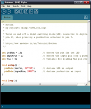
| − | ===Buzzer:===
| |
| | | | |
| − | [http://www.instructables.com/id/Play-the-French-Can-Can-Using-an-Arduino-and-Buzze/?ALLSTEPS source]
| + | <Gallery> |
| − | <source lang"C">
| + | Soubor:arduino fotka.jpg|[[Arduino - Compatible 8X Seven Segments Display|Compatible 8X Seven Segments Display]] |
| − | // Buzzer example function for the CEM-1203 buzzer (Sparkfun's part #COM-07950).
| + | Soubor:Arduiono-robot-pepik.jpg|[[Arduino - Jednoduchá aplikace|Jednoduchá aplikace - Robot Pepík - učebna D10]] |
| − | // by Rob Faludi
| + | Soubor:arduino-spsavos.jpg|[[Arduino - pohybující text: SPS a VOS|Pohybující text: SPS a VOS Pisek]] |
| − | // http://www.faludi.com
| + | |
| | | | |
| − | void setup() {
| + | Soubor:arduino-pocitadlo.jpg|[[Arduino - datumové počítadlo|Počítadlo: roky - měsíce - dny - hodiny - minuty - sekundy]] |
| − | pinMode(4, OUTPUT); // set a pin for buzzer output
| + | </Gallery> |
| − | }
| + | |
| | | | |
| − | void loop() {
| |
| − | buzz(4, 2500, 500); // buzz the buzzer on pin 4 at 2500Hz for 1000 milliseconds
| |
| − | delay(1000); // wait a bit between buzzes
| |
| − | }
| |
| | | | |
| − | void buzz(int targetPin, long frequency, long length) {
| |
| − | long delayValue = 1000000/frequency/2; // calculate the delay value between transitions
| |
| − | //// 1 second's worth of microseconds, divided by the frequency, then split in half since
| |
| − | //// there are two phases to each cycle
| |
| − | long numCycles = frequency * length/ 1000; // calculate the number of cycles for proper timing
| |
| − | //// multiply frequency, which is really cycles per second, by the number of seconds to
| |
| − | //// get the total number of cycles to produce
| |
| − | for (long i=0; i < numCycles; i++){ // for the calculated length of time...
| |
| − | digitalWrite(targetPin,HIGH); // write the buzzer pin high to push out the diaphram
| |
| − | delayMicroseconds(delayValue); // wait for the calculated delay value
| |
| − | digitalWrite(targetPin,LOW); // write the buzzer pin low to pull back the diaphram
| |
| − | delayMicroseconds(delayValue); // wait againf or the calculated delay value
| |
| − | }
| |
| − | }
| |
| − |
| |
| − | </source>
| |
| − |
| |
| − | ===Jednoduchá aplikace pro Arduino:===
| |
| − |
| |
| − |
| |
| − | <source lang"C">
| |
| − | /*
| |
| − | * Robot Pepík - učebna D10
| |
| − | * Tento program zobrazuje čas, který uběhl od spuštění programu
| |
| − | * - při každé 0té sekundě popojede dopředu
| |
| − | * - při každé první sekundě se zastaví
| |
| − | * - při každé desáté sekundě popojede zpět
| |
| − | * - při každé jedenácté sekundě se zastaví
| |
| − | */
| |
| − |
| |
| − | // přiložení knihovny pro práci s LCD
| |
| − | #include <LiquidCrystal.h>
| |
| − |
| |
| − | // inicializace LCD - nastavení používaných pinů
| |
| − | LiquidCrystal lcd(11, 9, 5, 4, 3, 2);
| |
| − |
| |
| − | //inicializace portů DC Motorů
| |
| − | int motor_left[] = {6, 7};
| |
| − | // pole obsahující ovládací piny levého motoru
| |
| − | int motor_right[] = {8, 10}; // pole obsahující ovládací piny pravého motoru void setup() { //DC motory - počáteční nastavení
| |
| − |
| |
| − | int i; for(i = 0; i < 2; i++){
| |
| − | pinMode(motor_left[i], OUTPUT);
| |
| − | pinMode(motor_right[i], OUTPUT);
| |
| − | }
| |
| − |
| |
| − | lcd.begin(16, 2); // nastavení rozsahu LCD monitoru
| |
| − |
| |
| − | lcd.setCursor(0, 0); // nastavení kurzoru na LCD na pozici 0:0
| |
| − | lcd.print("Minuty:"); // vytiskne text na LCD
| |
| − |
| |
| − | lcd.setCursor(0, 1); // nastavení kurzoru na LCD na pozici 0:0
| |
| − | lcd.print("Sekundy:"); // vytiskne text na LCD
| |
| − | }
| |
| − |
| |
| − | void loop() { // tato funkce se neustále opakuje
| |
| − | int sekundy = (millis()/1000); // zjištění a výpočet doby, od spuštění programu - v sekundách
| |
| − | int minuty = millis()/1000/60; // zjištění a výpočet doby, od spuštění programu - v minutách
| |
| − | sekundy -= minuty*60; // korekce času - po 60ti sekundách se sekundy vynulují
| |
| − | if(sekundy == 0) // když se sekundy rovnají 0, display se vymaže
| |
| − | {
| |
| − | lcd.setCursor(10, 0);
| |
| − | lcd.print(" ");
| |
| − |
| |
| − | lcd.setCursor(10, 1);
| |
| − | lcd.print(" ");
| |
| − |
| |
| − | drive_forward(); // v nulté sekundě se motor vždy rozjede dopředu
| |
| − | }
| |
| − |
| |
| − | lcd.setCursor(10, 0); // nastaví pozici kurzoru na LCD
| |
| − | lcd.print(minuty); // vytiskne čas, který uběhl od spuštění programu v minutách
| |
| − |
| |
| − | if(sekundy==1) // v první sekundě se motor vždy zastavý
| |
| − | {
| |
| − | motor_stop();
| |
| − | }
| |
| − | if(sekundy == 10) // v desáté sekundě se motor vždy rozjede dozadu
| |
| − | {
| |
| − | drive_backward();
| |
| − | }
| |
| − | if(sekundy == 11) // v jedenácté sekundě se motor vždy zastavý
| |
| − | {
| |
| − | motor_stop();
| |
| − | }
| |
| − |
| |
| − | lcd.setCursor(10, 1);
| |
| − | lcd.print(sekundy); // vytiskne čas, který uběhl od spuštění programu v sekundách
| |
| − | }
| |
| − |
| |
| − | void motor_stop(){ //zastaví DC motory
| |
| − | digitalWrite(motor_left[0], LOW);
| |
| − | digitalWrite(motor_left[1], LOW);
| |
| − |
| |
| − | digitalWrite(motor_right[0], LOW);
| |
| − | digitalWrite(motor_right[1], LOW);
| |
| − | delay(25);
| |
| − | }
| |
| − |
| |
| − | void drive_forward(){ //zapne DC motory směrem dopředu
| |
| − | digitalWrite(motor_left[0], HIGH);
| |
| − | digitalWrite(motor_left[1], LOW);
| |
| − |
| |
| − | digitalWrite(motor_right[0], HIGH);
| |
| − | digitalWrite(motor_right[1], LOW);
| |
| − | }
| |
| − |
| |
| − | void drive_backward(){ //zapne DC motory směrem vzad
| |
| − | digitalWrite(motor_left[0], LOW);
| |
| − | digitalWrite(motor_left[1], HIGH);
| |
| − |
| |
| − | digitalWrite(motor_right[0], LOW);
| |
| − | digitalWrite(motor_right[1], HIGH);
| |
| − | }
| |
| − |
| |
| − | void turn_left(){ //zapne DC motory a zatočí vlevo
| |
| − | digitalWrite(motor_left[0], LOW);
| |
| − | digitalWrite(motor_left[1], HIGH);
| |
| − |
| |
| − | digitalWrite(motor_right[0], HIGH);
| |
| − | digitalWrite(motor_right[1], LOW);
| |
| − | }
| |
| − |
| |
| − | void turn_right(){ //zapne DC motory a zatočí vpravo
| |
| − | digitalWrite(motor_left[0], HIGH);
| |
| − | digitalWrite(motor_left[1], LOW);
| |
| − |
| |
| − | digitalWrite(motor_right[0], LOW);
| |
| − | digitalWrite(motor_right[1], HIGH);
| |
| − | }
| |
| − | </source>
| |
| − |
| |
| − | == Arduino Compatible 8X Seven Segments Display ==
| |
| − |
| |
| − |
| |
| − | [[Soubor:Arduiono-7disp.jpg|300px]] [[Soubor:arduino fotka.jpg|300px]]
| |
| − |
| |
| − | Integrovaná tlačítka, LED & 7 segmentový display
| |
| − | - Vyžaduje pouze 3 IO výstupy k činnosti
| |
| − | - TM1638 chip micro-8 8-segment LED displayů a 8 tlačítek a 8 testovacíhc dvoubarevných Led kontrolek, IO zajišťují sériovou komunikaci rozhraní, 8 nastavovacích úrovní jasu.
| |
| − | Specifikace: 0.2 cm x 5.0 cm x 1.0 cm
| |
| − |
| |
| − | Programuje se v progamu Arduino pomoc jazyka C++ (možno sáhnout zde http://arduino.cc/en/Main/Software). V programu Arduino můžete také načíst funkční příklady z knihovny (možno stáhnout zde http://code.google.com/p/tm1638-library/)
| |
| − |
| |
| − | '''Příklad pro funkční modul'''
| |
| − | <source lang"C">
| |
| − | #include <TM1638.h>
| |
| − | #include <InvertedTM1638.h>
| |
| − |
| |
| − | #define NO_MODULES 2
| |
| − |
| |
| − | // define a regular module and a inverted module
| |
| − | TM1638 module1(3, 2, 4);
| |
| − | InvertedTM1638 module2(3, 2, 5);
| |
| − | TM1638* modules[NO_MODULES] = {
| |
| − | &module1,
| |
| − | &module2
| |
| − | };
| |
| − | byte modes[NO_MODULES];
| |
| − |
| |
| − | unsigned long startTime;
| |
| − |
| |
| − | void setup() {
| |
| − | startTime = millis();
| |
| − |
| |
| − | for (int i = 0; i < NO_MODULES; i++) {
| |
| − | modules[i]->setupDisplay(true, 7);
| |
| − | modes[i] = 0;
| |
| − | }
| |
| − | }
| |
| − |
| |
| − | void update(TM1638* module, byte* mode) {
| |
| − | byte buttons = module->getButtons();
| |
| − | unsigned long runningSecs = (millis() - startTime) / 1000;
| |
| − |
| |
| − | // button pressed - change mode
| |
| − | if (buttons != 0) {
| |
| − | *mode = buttons >> 1;
| |
| − | module->clearDisplay();
| |
| − | module->setLEDs(0);
| |
| − | }
| |
| − |
| |
| − | switch (*mode) {
| |
| − | case 0:
| |
| − | module->setDisplayToDecNumber(runningSecs, 1 << 7);
| |
| − | break;
| |
| − | case 1:
| |
| − | module->setDisplayToDecNumber(runningSecs, 1 << 6, false);
| |
| − | break;
| |
| − | case 2:
| |
| − | module->setDisplayToHexNumber(runningSecs, 1 << 5);
| |
| − | break;
| |
| − | case 4:
| |
| − | module->setDisplayToHexNumber(runningSecs, 1 << 4, false);
| |
| − | break;
| |
| − | case 8:
| |
| − | module->setDisplayToBinNumber(runningSecs, 1 << 3);
| |
| − | break;
| |
| − | case 16:
| |
| − | module->clearDisplayDigit((runningSecs - 1) % 8, 0);
| |
| − | module->setDisplayDigit(runningSecs % 8, runningSecs % 8, 0);
| |
| − | break;
| |
| − | case 32:
| |
| − | char s[8];
| |
| − | sprintf(s, "Secs %03d", runningSecs % 999);
| |
| − | module->setDisplayToString(s);
| |
| − | break;
| |
| − | case 64:
| |
| − | if (runningSecs % 2 == 0) {
| |
| − | module->setDisplayToString("TM1638 ");
| |
| − | } else {
| |
| − | module->setDisplayToString("LIBRARY ");
| |
| − | }
| |
| − |
| |
| − | module->setLED(0, (runningSecs - 1) % 8);
| |
| − | module->setLED(1 + runningSecs % 3, runningSecs % 8);
| |
| − | break;
| |
| − | case 65:
| |
| − | module->setDisplayToError();
| |
| − | break;
| |
| − |
| |
| − | }
| |
| − | }
| |
| − |
| |
| − | void loop() {
| |
| − | for (int i = 0; i < NO_MODULES; i++) {
| |
| − | update(modules[i], &modes[i]);
| |
| − | }
| |
| − | }
| |
| − |
| |
| − | </source>
| |
| − | '''Jednoduchý příklad pro jedno Arduino'''
| |
| − | <source lang"C">
| |
| − | #include <TM1638.h>
| |
| − |
| |
| − | // define a module on data pin 3, clock pin 2 and strobe pin 4
| |
| − | TM1638 module(3, 2, 4);
| |
| − |
| |
| − | void setup() {
| |
| − | // display a hexadecimal number and set the left 4 dots
| |
| − | module.setDisplayToHexNumber(0x1234ABCD, 0xF0);
| |
| − | }
| |
| − |
| |
| − | void loop() {
| |
| − | byte keys = module.getButtons();
| |
| − |
| |
| − | // light the first 4 red LEDs and the last 4 green LEDs as the buttons are pressed
| |
| − | module.setLEDs(((keys & 0xF0) << 8) | (keys & 0xF));
| |
| − | }
| |
| − | </source>
| |
| − |
| |
| − | '''Příklad pro pohybující se text'''- zde se bude psát SPS A VOS PISEK, nápis lze změnit jednoduchým přepsáním textu const char string, rychlost pohybu textu určuje delay
| |
| − | <source lang"C">
| |
| − | #include <TM1638.h>
| |
| − |
| |
| − | #define MODULES 4
| |
| − |
| |
| − | // define a modules
| |
| − | TM1638 modules[] = {
| |
| − | TM1638(3, 2, 4),
| |
| − | TM1638(3, 2, 5),
| |
| − | TM1638(8, 9, 5),
| |
| − | TM1638(8, 9, 4)
| |
| − | };
| |
| − |
| |
| − | void setup() {
| |
| − | }
| |
| − |
| |
| − | const char string[] = " SPS A VOS PISEK ";
| |
| − | int base = 0;
| |
| − |
| |
| − | void loop() {
| |
| − | for (int i = 0; i < MODULES; i++) {
| |
| − | const char* pos = string + base + (i * 8);
| |
| − |
| |
| − | if (pos >= string && pos + 8 < string + sizeof(string)) {
| |
| − | modules[i].setDisplayToString(pos);
| |
| − | } else {
| |
| − | modules[i].clearDisplay();
| |
| − | }
| |
| − | }
| |
| − |
| |
| − | base++;
| |
| − |
| |
| − | if (base == sizeof(string) - 8) {
| |
| − | base = -MODULES * 8;
| |
| − | }
| |
| − |
| |
| − | delay(300);
| |
| − | }
| |
| − |
| |
| − | </source>
| |
| − |
| |
| − | '''Příklad pro dva Displaye'''
| |
| − | <source lang"C">
| |
| − | #include "TM1638.h"
| |
| − |
| |
| − | // hello segments for display
| |
| − | const byte hello[] = {
| |
| − | 0b00000000, 0b01110110, 0b01111001, 0b00111000, 0b00111000, 0b00111111, 0b00000000, 0b00000000
| |
| − | };
| |
| − |
| |
| − | // define the first module
| |
| − | TM1638 module1(3, 2, 4);
| |
| − | // to chain modules, use the same clk and data - just specify a different strobe pin
| |
| − | TM1638 module2(3, 2, 5);
| |
| − |
| |
| − | unsigned long value = 0L;
| |
| − | boolean state = true;
| |
| − |
| |
| − | void setup()
| |
| − | {
| |
| − | // display the hello segments on module 1
| |
| − | module1.setDisplay(hello);
| |
| − | // display the hello segments on module 2
| |
| − | module2.setDisplay(hello);
| |
| − |
| |
| − | // light the lower 5 red LEDs and the top 5 green LEDs
| |
| − | module1.setLEDs(0b00011111 | 0b11111000 << 8);
| |
| − |
| |
| − | // light the 3rd red LED
| |
| − | module2.setLED(TM1638_COLOR_RED, 3);
| |
| − | // light the 5th green LED
| |
| − | module2.setLED(TM1638_COLOR_GREEN, 5);
| |
| − | // light the 7th red and green LEDs
| |
| − | module2.setLED(TM1638_COLOR_RED | TM1638_COLOR_GREEN, 7);
| |
| − | }
| |
| − |
| |
| − | void loop()
| |
| − | {
| |
| − | byte key1, key2;
| |
| − |
| |
| − | // read the buttons from the first module
| |
| − | key1 = module1.getButtons();
| |
| − | // read the buttons from the second module
| |
| − | key2 = module2.getButtons();
| |
| − |
| |
| − | // both pressed
| |
| − | if (key1 != 0 && key2 != 0) {
| |
| − | value = 0;
| |
| − |
| |
| − | // set the display to 0 on both modules if they have buttons pressed simultaneously
| |
| − | module1.setDisplayToHexNumber(value, 0b10101010);
| |
| − | module2.setDisplayToDecNumber(value, 0b01010101);
| |
| − | } else {
| |
| − | // check the first module buttons
| |
| − | if (key1 != 0) {
| |
| − | // show the pressed buttons of the first module on its display
| |
| − | module2.setDisplayToBinNumber(key1, 0);
| |
| − | // and on the LEDs
| |
| − | module1.setLEDs(key1);
| |
| − |
| |
| − | // check to see if it's the last button pressed
| |
| − | if (key1 & 128) {
| |
| − | // toggle the display state on/off
| |
| − | state = !state;
| |
| − | delay(200); // just wait for button up
| |
| − | }
| |
| − |
| |
| − | // set the intensity and display state
| |
| − | module1.setupDisplay(state, key1 >> 1);
| |
| − | }
| |
| − |
| |
| − | // check the second module buttons
| |
| − | if (key2 != 0) {
| |
| − | // just add it to the display value
| |
| − | value += key2;
| |
| − |
| |
| − | // display it as an hexadecimal on the first module
| |
| − | module1.setDisplayToHexNumber(value, 0b10101010);
| |
| − | // and as a decimal on the second module
| |
| − | module2.setDisplayToDecNumber(value, 0b01010101);
| |
| − |
| |
| − | // light the LEDs
| |
| − | module2.setLEDs(key2 << 8);
| |
| − | }
| |
| − | }
| |
| − | }
| |
| − |
| |
| − | </source>
| |
| − |
| |
| − | '''Počítadlo roky - měsíce - dny - hodiny - minuty - sekundy'''
| |
| − |
| |
| − | <source lang"C">
| |
| − | #include "TM1638.h"
| |
| − |
| |
| − | TM1638 module1(3, 2, 4);
| |
| − | TM1638 module2(3, 2, 5);
| |
| − |
| |
| − | int sec = 0;
| |
| − | int minu = 0;
| |
| − | int hour = 0;
| |
| − |
| |
| − | int day = 0;
| |
| − | int mon = 0;
| |
| − | int year = 0;
| |
| − |
| |
| − | void setup()
| |
| − | {
| |
| − | }
| |
| − |
| |
| − | void loop()
| |
| − | {
| |
| − | if (sec == 60) { sec = 0; minu++; }
| |
| − | if (minu == 60) { minu = 0; hour++; }
| |
| − | if (hour == 24) { hour = 0; day++; }
| |
| − |
| |
| − | if (day == 32) { day = 0; mon++; } // 31 dnu = mesic
| |
| − | if (mon == 13) { mon = 0; year++; }
| |
| − | if (year == 100) year = 0;
| |
| − |
| |
| − | module1.setDisplayToString(((day < 10) ? "0" : "") + (String)day + "-" + ((mon < 10) ? "0" : "") + (String)mon + "-" + ((year < 10) ? "0" : "") + (String)year);
| |
| − | module2.setDisplayToString(((hour < 10) ? "0" : "") + (String)hour + "-" + ((minu < 10) ? "0" : "") + (String)minu + "-" + ((sec < 10) ? "0" : "") + (String)sec);
| |
| − |
| |
| − | sec++;
| |
| − |
| |
| − | delay(1000);
| |
| − | }
| |
| − | </source>
| |
| | [[Kategorie:SW]] | | [[Kategorie:SW]] |
| | [[Kategorie:HW]] | | [[Kategorie:HW]] |
| | [[Kategorie:MIT]] | | [[Kategorie:MIT]] |